
The relay is the most useful part in our toolbox. It solves more wiring problems than any other single component: starter interrupts, trigger reversal, driving a load the tracker can't drive on its own, turning a pulse into a constant output, and more. If you understand the relay, you can isolate a circuit, switch a circuit, or interrupt a circuit anywhere in the vehicle.
A relay is an electromechanical switch. When power and ground are applied to the two ends of its coil, the coil creates a magnetic field. That field pulls a set of contacts closed (or open), which completes or breaks a separate circuit.
The relay's best feature is that a very small amount of current can switch a very large amount of current. A tracker's output wire may only be able to source 200 to 500 milliamps. A relay lets that tiny output control a 30 amp circuit.
This is also why vehicle manufacturers use relays everywhere. Headlights, fuel pumps, starters, and blowers are all wired in the shortest possible run from the battery to the load, and a small wire runs from the switch to a relay. Less wire, smaller gauge, cheaper switches, and less voltage lost to resistance.
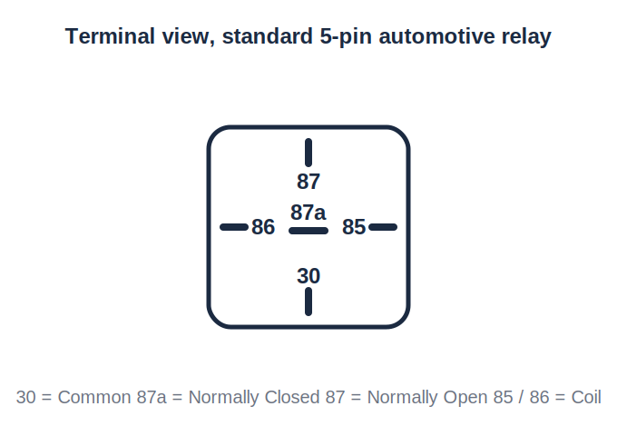
A standard automotive relay has five terminals, or pins. Think of it in two sections:
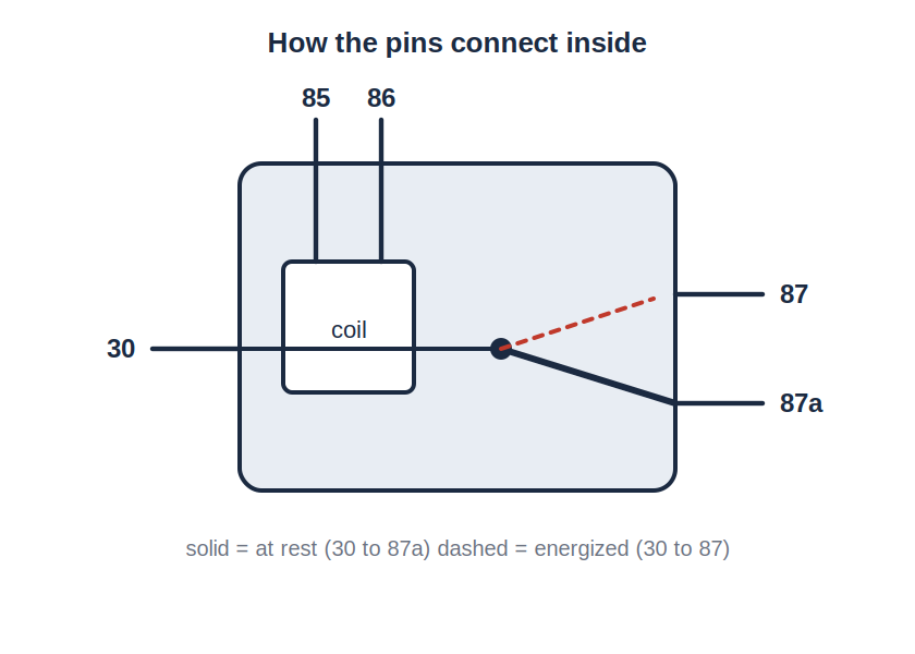
The coil: pins 85 and 86. Ground on one, 12 volts on the other, and the relay activates. It doesn't matter which pin gets which, unless the relay has a built-in diode or resistor (see below).
The contacts: pins 30, 87, and 87a.
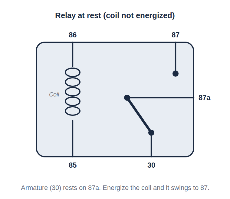
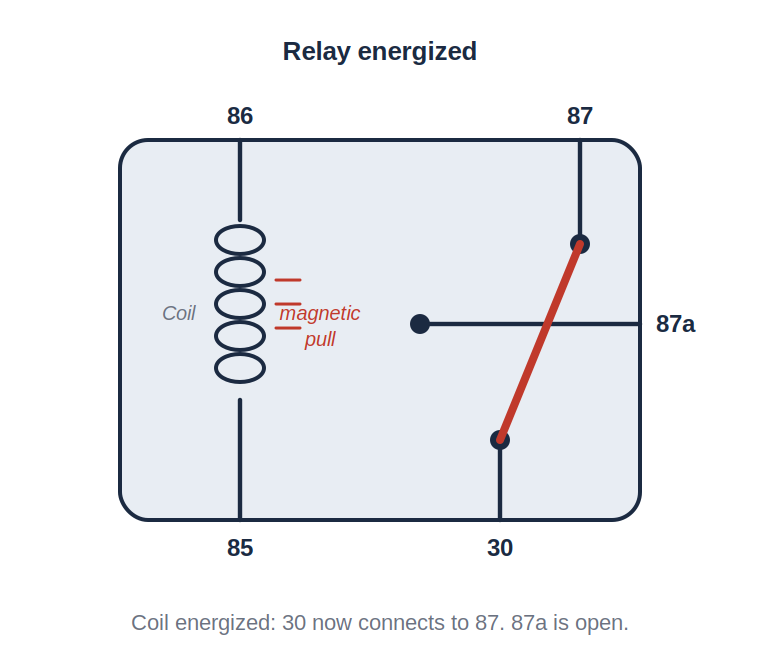
This type of relay is called Single Pole Double Throw, or SPDT. One pole (pin 30) can be thrown to two positions (87a or 87). It's the most flexible configuration and the one we use most.
Some relays only have four pins. They're SPST (Single Pole Single Throw): pins 85, 86, 30, and 87, with no 87a. They can only make a circuit, not break one.
A standard SPDT automotive relay's coil needs roughly 130 to 170 milliamps to activate. Call it 150 mA on average. That's well within what any tracker or dash cam output can supply.
On the contact side, the Normally Closed contact (87a) is typically rated at 30 amps and the Normally Open contact (87) at 40 amps. Always check the rating printed on the relay.
Some relays have a resistor or diode across the coil to absorb the voltage spike created when the coil de-energizes. Those with a resistor may need the full 170 mA. Those with a diode are polarity-sensitive: 86 must be positive and 85 must be ground, or the diode shorts and the relay dies. When you don't know, add your own diode (see the Diodes chapter) and wire 86 positive, 85 ground.
Every circuit below uses a standard SPDT relay unless noted. Test the vehicle circuit with a meter before connecting to it.
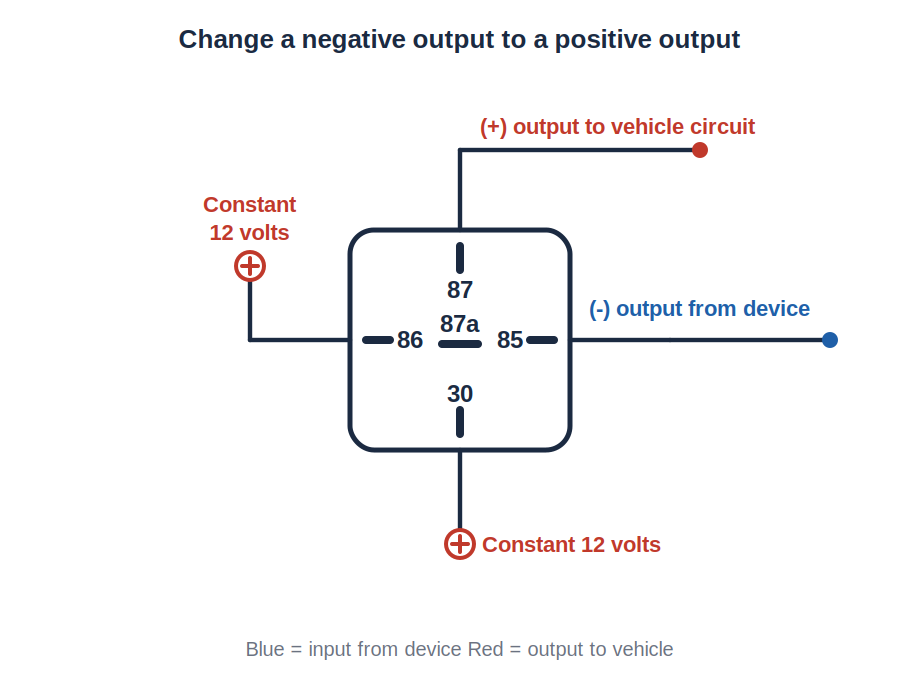
Many trackers give a negative (ground) output. Many vehicle circuits need a positive pulse. Wire the tracker's negative output to pin 85, constant 12 volts to pin 86, constant 12 volts to pin 30, and take your positive output off pin 87. When the tracker pulls 85 to ground, 30 connects to 87 and 12 volts goes out.
Use it for: driving a positive door lock circuit, a positive buzzer or lamp, or any positive-trigger input on another device.
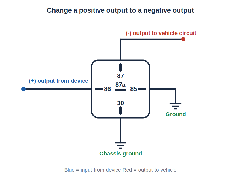
The reverse. Positive output from the device to pin 86, ground to pin 85, ground to pin 30, negative output off pin 87. Use it when a device gives a positive output and the circuit or the next device needs a ground.
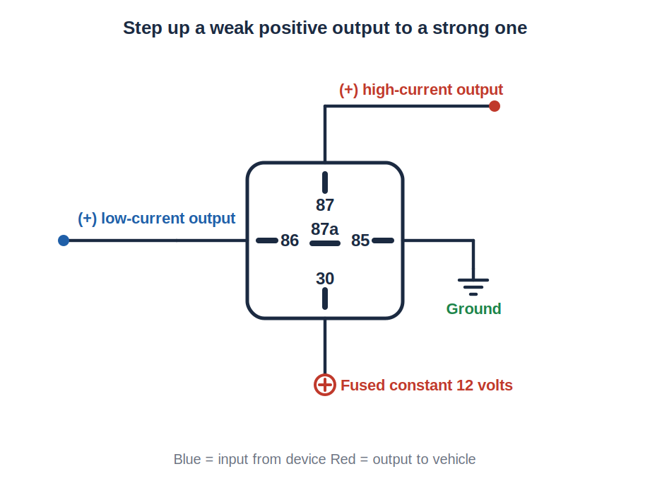
When a device's positive output can only handle a few hundred milliamps and you need to drive something heavier (a siren, a light bar, a beacon), run the weak output to pin 86, ground to 85, a fused constant 12 volt feed to pin 30, and take the strong output off pin 87. The relay does the heavy lifting.
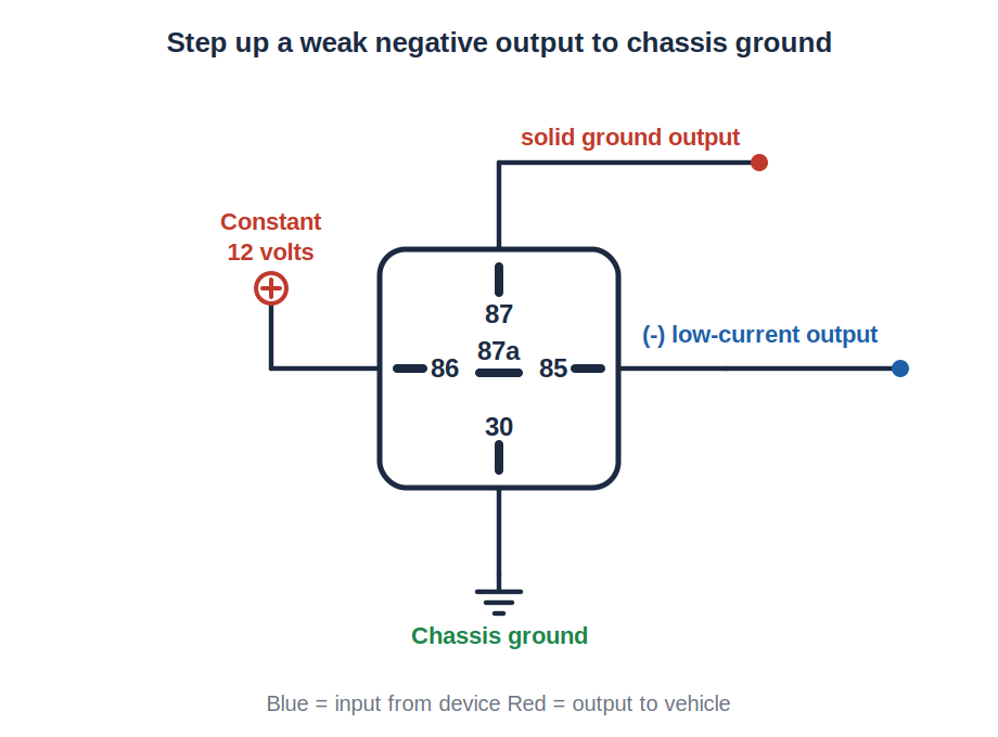
Same idea on the ground side. Weak negative output to pin 85, 12 volts to 86, chassis ground to 30, and pin 87 becomes a solid ground that can sink far more current than the device output could. This is the standard way to drive a starter interrupt relay from a tracker output that is only rated for 250 mA.
The most common relay job in fleet work. A tracker's immobilize output controls a relay placed in series with the starter signal wire.
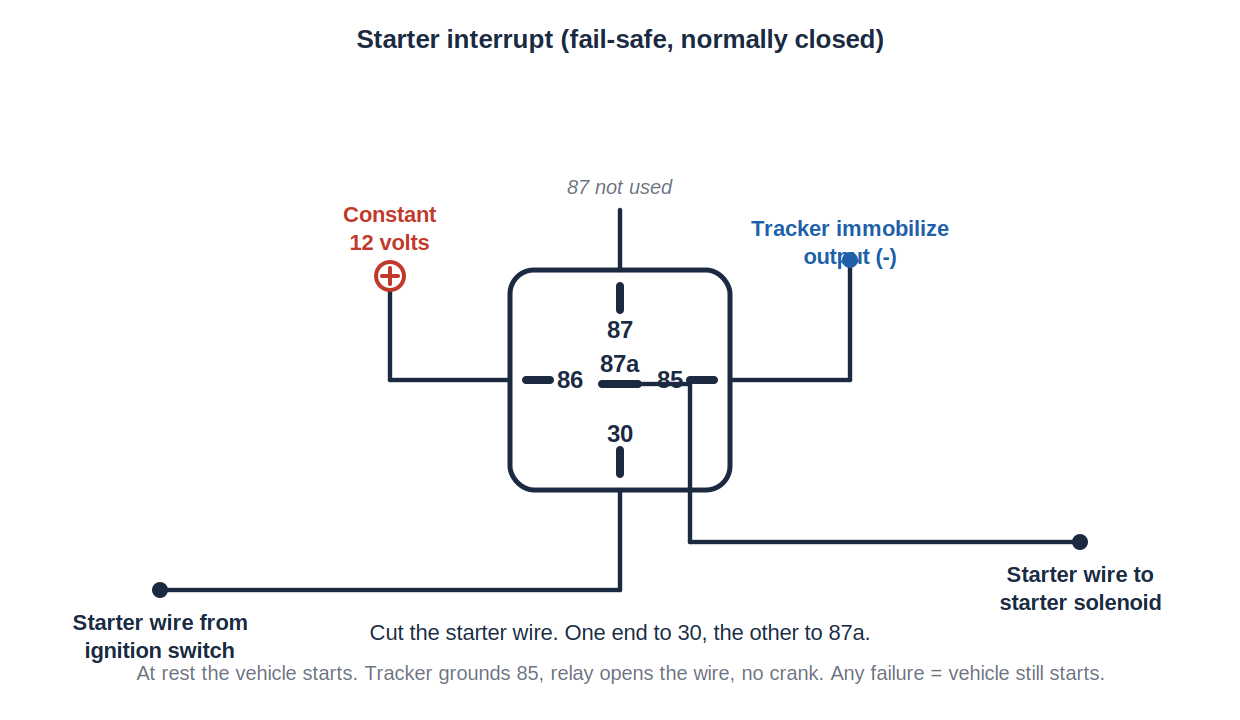
Cut the starter wire. One end goes to pin 30, the other to pin 87a. Constant 12 volts to pin 86. Tracker's immobilize output (negative) to pin 85.
At rest, 30 is connected to 87a and the vehicle starts normally. When the tracker pulls 85 to ground, the relay energizes, 30 swings to 87, and the starter circuit is open. The vehicle won't crank.
Wired this way, a relay failure or a tracker failure leaves the vehicle able to start. That's the fail-safe configuration we use. Never wire an immobilizer so a failure strands the vehicle.
If the starter wire carries more than the relay's rating, use the tracker output to drive a heavier relay, or use the step-up circuit above.
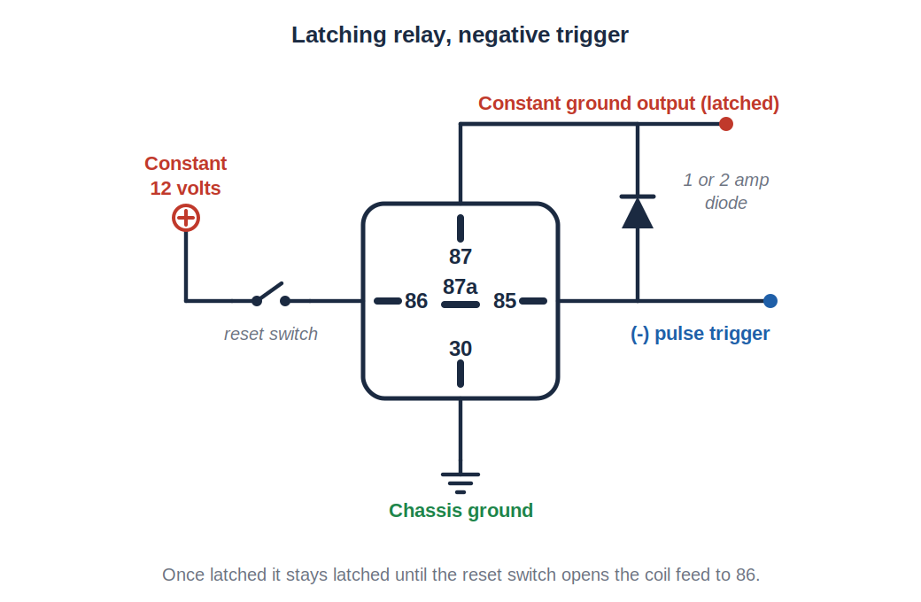
Turns a single negative pulse into a constant ground. One SPDT relay and a 1 or 2 amp diode. Once it latches, it stays latched until the constant 12 volt feed to pin 86 is interrupted.
Use it for: anything that needs a steady ground after a one-time pulse, such as a warning lamp that stays on until reset, or holding a circuit active after a momentary trigger.
To reset it, break the 12 volt feed to pin 86 with a momentary switch, or add a second relay wired normally closed in that feed so that when the second relay energizes, it opens the feed and unlatches the first.
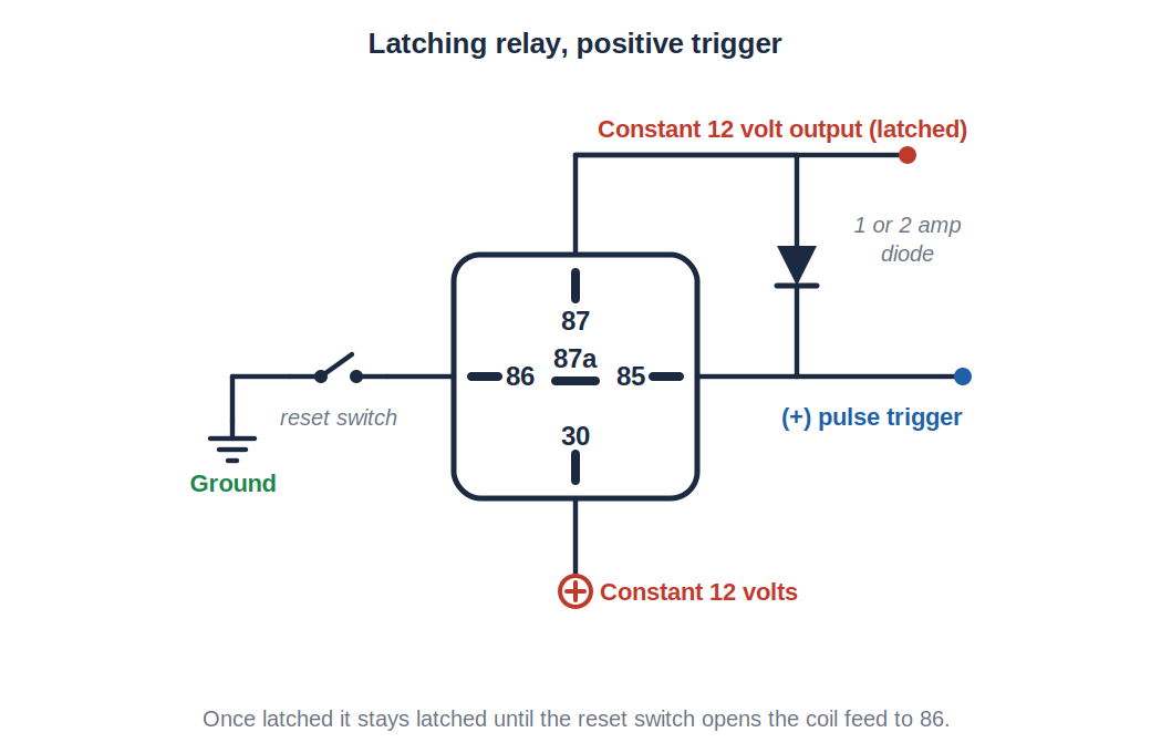
Same circuit flipped. A single positive pulse becomes a constant 12 volt output. It stays latched until the ground to pin 86 is interrupted. Same reset methods.
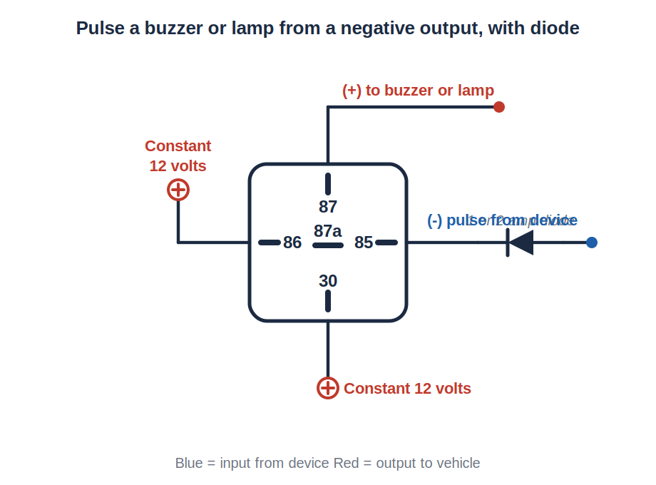
When a device gives a short negative pulse (a pre-warning, an alert output) and you want it to sound a buzzer or flash a lamp, use an SPDT relay with a 1 or 2 amp diode in the trigger line. The diode keeps the buzzer's circuit from feeding back into the device's output.
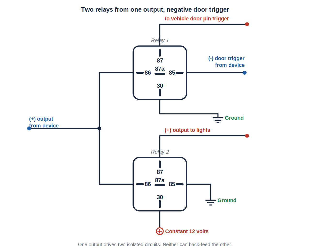
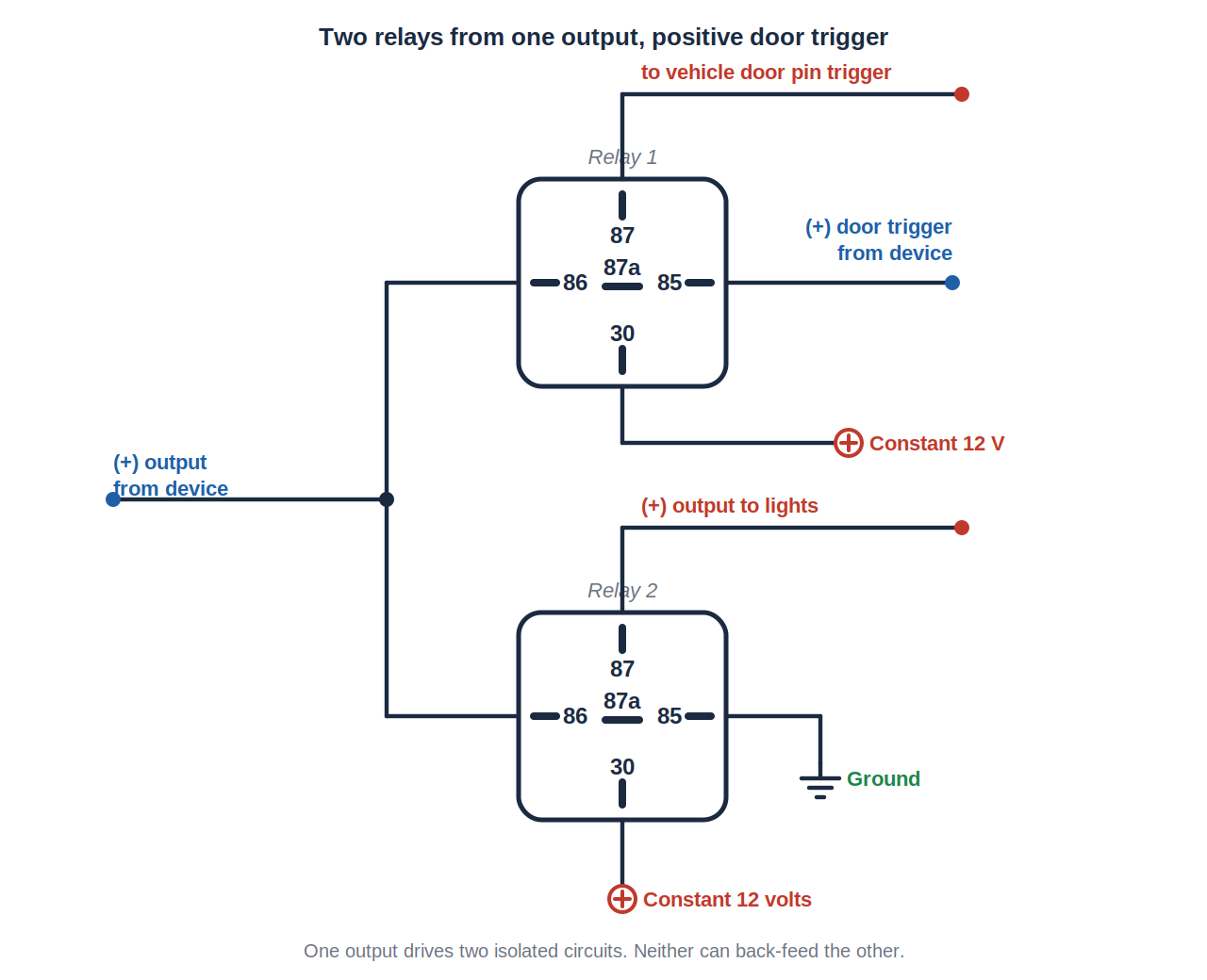
These two circuits show how to use a pair of SPDT relays to drive two separate loads from a single output while keeping them isolated from each other. One version is for vehicles with negative door triggers, the other for positive door triggers. The original use was alarm lighting. The same layout works any time one output needs to drive two circuits that must not back-feed each other.
Rather have us do it? We install GPS, dash cams and telematics across Georgia, South Carolina, North Carolina, Tennessee, Virginia, Alabama, Florida and Mississippi, at your yard. Get a free quote or call/text 803-513-1009.
This information is provided as a guide. Verify every circuit with a digital multimeter before connecting to it. Proper installation is the responsibility of the installer.
We install GPS, dash cams and telematics across GA, SC, NC, TN, VA, AL, FL & MS — at your yard, on your schedule.